EXHIBIT ENGINEERS · ZIGONG, CHINA
Train braking system exhibit — actual physical exhibit reference photograph

Robotics & Mechanical Models

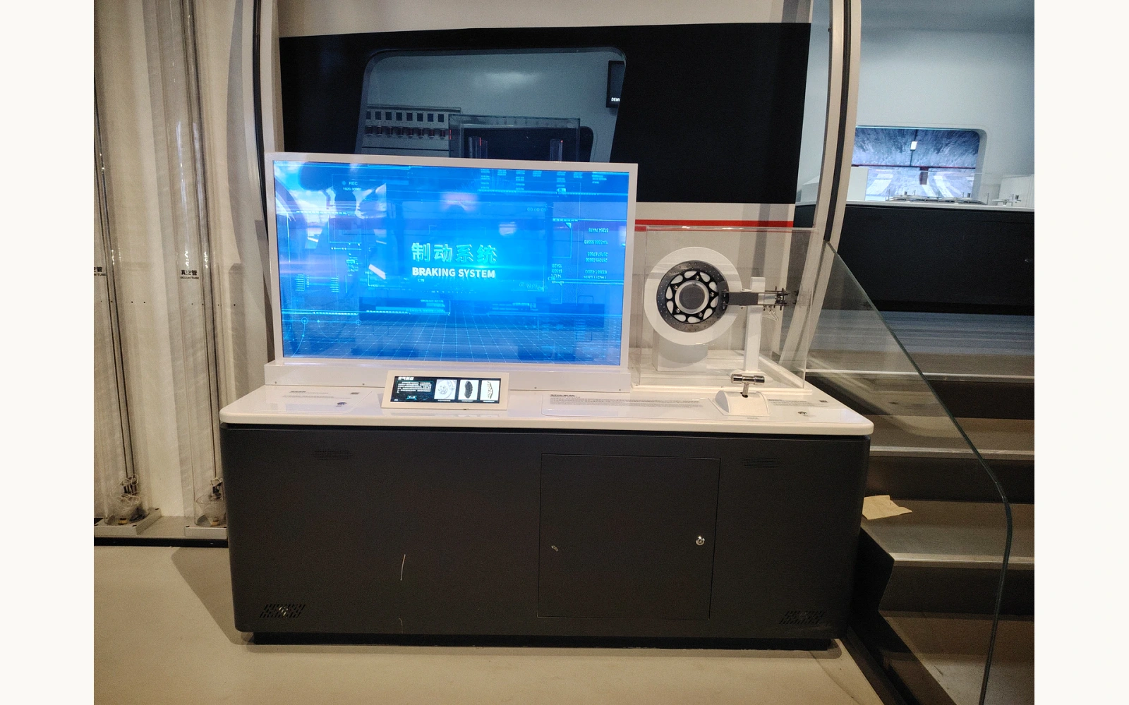
Train braking system exhibit

A covered railway braking model pairs a visible wheel assembly, screen and visitor controls, supporting a museum introduction to how vehicles slow and stop.

▶ Watch the film
17 sec · Real operating video

THE PRODUCT IN MOTION

See it work.

See the actual train braking system exhibit. A wheel-like mechanical assembly is displayed beside the screen. Use the front controls according to the demonstration instructions.

Video & text guide

THE ACTIVITY & MECHANISM

Explore how a railway vehicle slows down

A protected wheel-and-brake model sits beside visitor controls and explanatory media, giving visitors a physical reference for how vehicles slow down. The brake components, driven movement and operating modes require confirmation. Measured braking force and stopping distance have not been established for this configuration.

  1. 01

    Locate

    Identify the guarded wheel and its neighboring components.

  2. 02

    Activate

    Use the front controls according to the demonstration instructions.

  3. 03

    Explain

    Relate the visible sequence to the braking method named in the final script.

REFERENCE & PROJECT SCOPE

Reference specifications.

Use the reference dimensions and operating information to plan the exhibit. The agreed project drawings define the supplied configuration, installation interfaces and service access.

Approx. L × W × H
1,800 × 1,200 × 2,500 mm
Exhibit theme
Robotics & Mechanical Models
Visitor activity
Locate · Activate · Explain
Reference operation
Visitors operate the front brake control beside the guarded wheel-and-disc model and rear display. The handle drawing includes a return spring and limit switch; the final control-to-model response needs confirmation.
Power & supply
Powered versions can be configured for 110/220 V AC, 50/60 Hz. Keep the handle sweep and protective enclosure clear. Confirm the cabinet electrical connection, fixing points and service access for the handle return and limit-switch assembly.
Reference construction
The handle-assembly drawing lists Q235 steel support parts, stainless-steel links and decorative parts, a 45-grade steel shaft shell and a nylon resistance sleeve. This drawing does not specify the complete cabinet or brake-model materials.
Configuration options
Appearance, interpretation language, controls and installation arrangement by project agreement
Daily operating schedule
8 hours per day
Scheduled maintenance
Every 30 days
Factory dispatch lead time
30–120 calendar days after design approval and receipt of the deposit. Transit time is additional.
Minimum custom order
One exhibit

Approximate planning estimate: 1800 × 1200 × 2500 mm (L × W × H). Braking-model cabinet, guard, visitor controls, rear screen and curved support frame.

Reference configuration notes
Wheel assembly
A wheel-like mechanical assembly is displayed beside the screen.
Guarded mechanism
A transparent cover separates the assembly from visitor hands.
Front controls
Controls are positioned along the visitor edge of the cabinet.
Customisation, installation & support
01Reference envelope
Approximate planning estimate: 1800 × 1200 × 2500 mm (L × W × H). Braking-model cabinet, guard, visitor controls, rear screen and curved support frame.
02Configuration
Confirm the demonstrated brake type, model drive, moving clearances, control sequence and interpretation diagrams.
03Visitor access
Agree viewing positions, reach, approach space and supervision for the selected audience.
04Handover scope
Confirm the technical drawings, supplied media, service access and operating instructions before production.
See the design-to-delivery process

BEFORE AN ENQUIRY

Questions & support.

24 months of complimentary spare-parts support, remote technical guidance and long-term after-sales support. Exhibit Engineers pays the shipping cost of complimentary spare parts during the 24-month support period.

Explore the support
Delivery, installation & after-sales terms
Payment
A 50% deposit is payable after the contract is signed. The remaining balance is paid after acceptance and before dispatch, so full payment is received before dispatch. Payment methods are agreed in the contract.
Packaging & transport
Metal shipping cases or multilayer wood-panel shipping cases. Transport arrangements and costs are agreed to suit the project.
Materials & painted finish
Common material options include Q235 steel, stainless steel, aluminium alloy, PVC, acrylic, engineering plastics. The combination is selected for each configuration. Marine anti-corrosion paint with a piano-gloss automotive paint finish. Applied to painted parts.
Typical power · powered versions
Standard products: 100–500 W; oversized installations: 1,000–5,000 W. Typical ranges for powered versions. Confirm the selected model and final connected load.
Product maintenance
Inspect the handle pivot, return spring, limit-switch actuation, wheel-model mounts and protective enclosure. Check for free control movement and secure screen and cabinet fixings.
Installation & training
Complimentary training is available on site or remotely, according to project needs. If installation or on-site after-sales service is not included in the product price, the customer pays the actual travel expenses incurred, unless the contract provides otherwise.
Factory acceptance & handover
Mid-production and pre-dispatch checks are provided. Factory acceptance can take place in person at the factory or through acceptance videos. Installation and operating videos, written installation and operating instructions, drawings and a spare-parts list are provided.
Complimentary parts
24 months of complimentary spare-parts support, starting when the exhibit is handed over for use. Covers faults not caused by the user. User-caused or deliberate damage is excluded. Exhibit Engineers pays the shipping cost of complimentary spare parts during the 24-month support period.
Warranty & repair labour
The whole-exhibit warranty period and repair labour scope and charges are agreed in the contract.

Can we discuss a prototype or sample for a custom version?

Yes. Prototype testing and sample fabrication are available for custom projects. Discuss which functions or features you need to review for your version. The scope, cost and schedule are agreed for the project.

How prototype testing & samples work
How does a brake change the motion of a vehicle?

Braking can use friction or electrical methods to oppose motion and manage energy. Regenerative braking returns recovered energy to a supply or storage system. The reference does not establish which modes are fitted to this model.

Can the reference be adapted for our gallery?

Confirm the demonstrated brake type, model drive, moving clearances, control sequence and interpretation diagrams. The reference photographs show one configuration; the final project drawings define the supplied version.

What do the images and videos show?

The gallery labels photographs, video frames, renderings and the dimension drawing. Physical footage is identified separately.

FROM CONCEPT TO TURNKEY DELIVERY

Start with a reference. Shape your version.

Share the exhibit name, intended users and a plan or description of your setting. We can work through the experience and practical scope.

START WITH YOUR IDEA

Tell us about your project.

Start with what you have: an idea, a sketch, a reference video or a procurement brief.

Review your message before opening WhatsApp. You can attach drawings or reference videos there.

SAVE YOUR PROJECT REFERENCES

Your selected exhibits.

1 · Select2 · Project3 · Verify & download

Save the exhibits you like, then choose up to 20 products for one complimentary PDF. Your saved list stays in this browser.

Start with an exhibit you like.

Choose “Save” on a product card or product page. Return here to prepare your collection.

Browse products ↗
0 / 20 selected

Need more information?

WhatsApp +86 13881436360 ↗[email protected]